

DDCWP 4-Station Waterproof DC Controller - 9V Battery Operated
was
$237.00
Special Price
$159.00
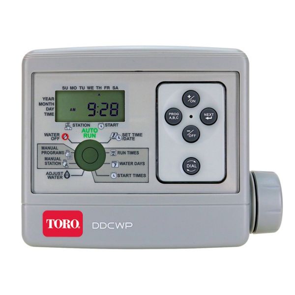
DDCWP 4-station waterproof DC irrigation controller powered by a single 9V battery. Designed for remote field installations without AC power. Operates DC latching solenoid valves only (will not run AC solenoids). Waterproof enclosure rated for direct burial or above-ground mounting. Runs one master valve and one station valve simultaneously.
| Stations | 4 |
|---|---|
| Power | 9V DC Battery |
| Solenoid Type | DC Latching only |
| Master Valve | Yes (1) |
| Enclosure | Waterproof |
| Dimensions | 5-3/4" W x 5" H x 1-15/16" D |
Availability:
Out of stock
SKU
DDCWP-4-9V
Ships Same Day
All orders placed by 12 PM local warehouse time will ship the same day. Some exclusions apply. Delivery time may increase if item isn't available in closest warehouse.
Delivery time: 2-4 business days
DDCWP® DC Controller, 4 Station Waterproof Battery Operated - 9V DC
Controller Specifications
The DDCWP will run one master valve and one station valve
simultaneously. The DDCWP is a DC controller. This means it ONLY runs DC latching solenoids - it will not run AC solenoids. As DC latching solenoids are more susceptible to debris than AC solenoids, Toro recommends that a filter be installed in the system upstream of the valves.
The DDCWP is tested to be operational under 2 meters of water and is marked IP68. It is important to completely dry the controller before opening the battery compartment. It is also important to make waterproof connections for the longevity of the system components. The DDCWP is supplied with 3M waterproof connectors for this purpose. If more connectors are required, Toro recommends 3M® DBY type connectors as these are readily available in most markets.
Connect all field wiring before applying battery power to the controller. This will insure that all connected DC solenoids are properly calibrated
for operation.
Dimensions
- 53/4” W x 5” H x 115/16” D
- Weight: 23.3 oz. without 9V battery
Programming Lock Out Feature
The DDCWP can be locked so that unauthorized programming can not occur. In the AUTO RUN position, press both +/ON and -/OFF buttons and hold for 5 seconds. The DDCWP will be "locked" in the AUTO RUN position. Repeat this sequence to "unlock" the DIAL button.
Automatic Voltage Detection
The DDCWP has an automatic voltage detection circuit. Before an irrigation start is initiated, this circuit checks battery voltage to insure that there is sufficient voltage remaining to shut the solenoids off. If there is not sufficient voltage, the program is cancelled and the low battery icon is
turned on in the LCD display.
About the DDCWP memory
This controller is equipped with "on board" back up battery that will keep the program memory for a few months in case power is not available. The 9 volt battery will turn on both displays and programming is possible. Do not remove batteries for winter months as program loss can occur.
Maximum Wire Runs for DDCWP Controller
With battery voltage at 9V DC and 7 Bars (105 PSI) of pressure at the valve, these are the maximum wire runs for an 8 station DDCWP:
- AWG # 18 (1.0mm2) multi-strand wire – 60m (197')
- AWG # 16 (1.5mm2) multi-strand wire – 100m (305')
- AWG # 14 (2.5mm2) multi-strand wire – 150m (493')
- AWG # 12 (4.0mm2) multi-strand wire – 250m (820')
Installation Instructions
-
Level and mount controller mounting bracket to a solid surface. If mounting in a valve box, it is suggested to mount the bracket under the lid and leave sufficient wire so the lid can be removed to access the controller.
-
Next connect the solenoid wires to the controller. The controller drives Toro latching solenoids. It is essential for proper operation that the wire colors between the solenoid and the controller be matched. The red controller station wire is connected to the red solenoid wire and the black controller common wire is attached to the black solenoid wire. It is also essential that a waterproof wire connection be made. The DDCWP is shipped with waterproof connectors for this purpose. These can be used for wire sizes 19 to 26 AWG. (0.9 metric is the largest size wire these accept)
-
After the station wires are connected, remove the battery compartment waterproof cap and take out the two 9VDC connectors. Attach two 9VDC alkaline batteries (not supplied) to the battery connectors, insert them into the battery compartment, replace the battery compartment cap and turn it clockwise to its locked position. It is important to add or change batteries with the controller in a dry condition. If moisture gets into the battery compartment, it can lead to deterioration of the batteries.